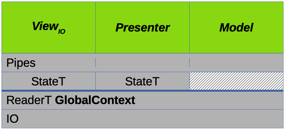
In the last couple of posts the architecture of osabe WAV editor was developed: an MVP implementation atop a stack of monads:
In the introductory post of this blog Functional Reactive Programming (FRP) was also mentioned as being used in the UI, in conjunction with the MVP pattern. In this post we're going to go over why FRP was used and how the UI was implemented using it, at various levels, after which we'll do a little analysis.
Motivation
Once the program was able to display a waveform, some rudimentary interactivity was added to allow panning of the view to test the waters of implementing a UI. This consisted of using a couple of state variables to keep track of the mouse's position and the depression state of the left mouse-button to determine whether the user was dragging and if so by how much, updating the Model appropriately.
All of this state was kept in the Presenter (since that's where UI logic is supposed to reside in the MVP pattern).
The panning functionality worked, but to continue implementing further interactivity using discrete state variables like this seemed like the wrong thing to do given the complexity of what had been envisioned for the UI -- I could just feel the impending burden of the code required.
Over the years I'd done a bit of reading about FRP and had used stream-processing in OO languages and this situation seemed like an appropriate occasion to employ the technique.
For those unfamiliar with it, reactive programming treats certain things, e.g. a mouse's position, as time-varying signals or streams. These streams can be transformed, split, combined, etc. to form a processing network that automatically reacts to changes in any of the input signals to produce a concerted output.
In this application I figured the mouse's position, the mouse button states, meta-key states, and the window size could all be streams fueled by the user's input and the processing network of the UI would react to changes in these signals to update the Model and generate visual output for the View.
While I wasn't sure at first how feasible it would be to implement UI components with it, FRP felt intuitively like the way to go, so I decided to try it and I'm pretty happy with how things turned out.
UI Implementation
For the most part in this blog we've been covering the construction of this application chronologically, but the development of the UI was kinda haphazard, so to relate the implementation here we're going to do a structured overview instead, starting at a high level and then working our way down:
FRP Integration with the MVP
Internally FRP is concerned with manipulating and using streams of data, but externally (for the implementation used in this application at least) it's just another stateful computation.
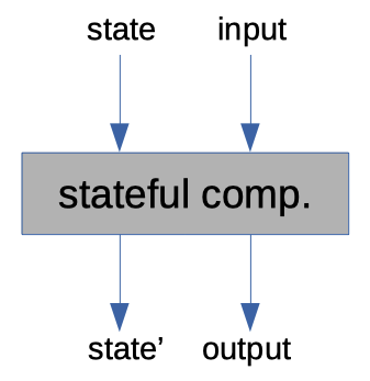
State in functional programming is often simulated in a function by adding an extra input and having an extra output; the state the operation needs to access is passed in along with all of the other function inputs and a new state value is returned along with the actual output of the function that contains any modifications made to it during the operation:
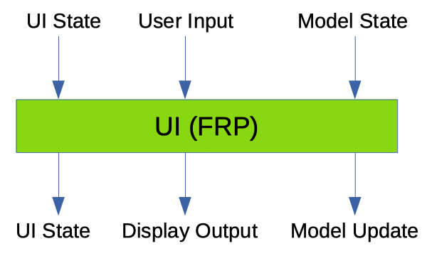
In our case, the state passed to the UI function is the stateful network of wired-together stream-processors and the inputs are the user's input from the View and a representation of the state of the Model. The UI operation feeds the View input and Model state to the network to drive its internal data streams, and the outputs from the network -- updates to run on the Model and a description of what to display in the View -- are returned from the function along with the new (post run) stateful network:
This operation can be integrated with the MVP components pretty directly, like so:
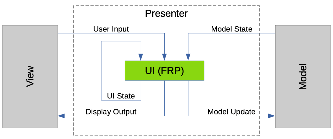
While this setup looks ok and does work, there's one major issue with it: it's inherently laggy.
To see why, let's consider an example:
Suppose a user is panning the waveform around. The input from the View side would be a mouse movement message, and input from the Model would be a view of the waveform in state n. After the FRP network is run, the output would be a representation of the system in state n for the View to display and an update message to make the Model transition from state n to state n+1, to adjust the position of the view of the waveform.
Wrapping back around to the top, the user is still panning so we get another input of mouse movement and we get a representation of the Model in state n+1; but here there's a mismatch: the output on the screen, which was generated from state n, is a step behind the current Model state of n+1 -- the user is seeing and reacting to outdated visual output! In fact, the user won't see the visual representation resulting from their previous action until after their current input is processed by the UI!
To remedy this, we need a strategic delay: rather than generate the output for the View directly from our FRP network, we'll have it return a display-description-producing function. To produce a description of what to display in the View, then, we'll take the Model update outputted by the network and apply it to the Model, read the new state, pass that to the description-producing function, and finally send the description output back to the View, like so:
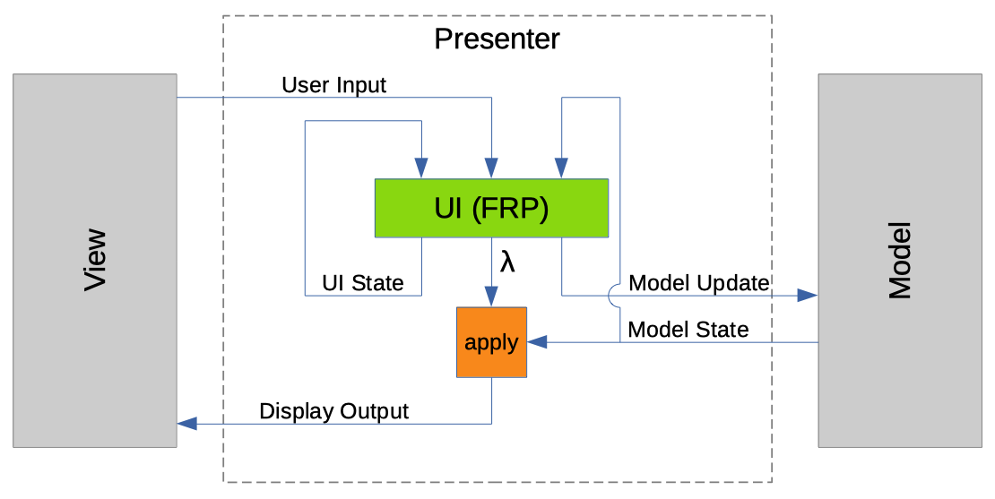
Now the user gets more immediate feedback from their input and the UI feels more responsive.
An alternative to using a delay here might be to run the Model update on the state that was passed to the UI operation before generating the output for the View, but then the update would have to be reapplied to the Model, duplicating the effort. Or, if this code were not purely functional then the UI operation might update the Model directly, in response to user input, before generating output for the View. But as things are, we're using a delay, imbuing this code with a good allocation of responsibilties and keeping it functionally pure.
The UI as Assembled Components
With this higher-level perspective in mind, let's step into the UI FRP network and consider that at a high level.
The visual UI of this application is divided into discrete areas, each of which reacts to user input differently and produces a different output on the screen. In addition, the UI has other reactions to user input that may not be tied to any specific area of the screen, such as stopping playback.
To realize these different behaviors we use distinct reactive stream-processing elements that we'll call components to transform the UI input stream into different output streams.
Since there are two basic types of output a component might have -- either with or without visual content -- I've categorized the components of this application into one of two types: Panels or Controls.
Panels take the network inputs and produce output for the View along with updates for the Model (called Feedback in the code) and Controls produce only Feedback for the Model and nothing for the View.
Components are assembled together to form the UI network by replicating the network's input across them and combining their outputs into a single output for the network as a whole:
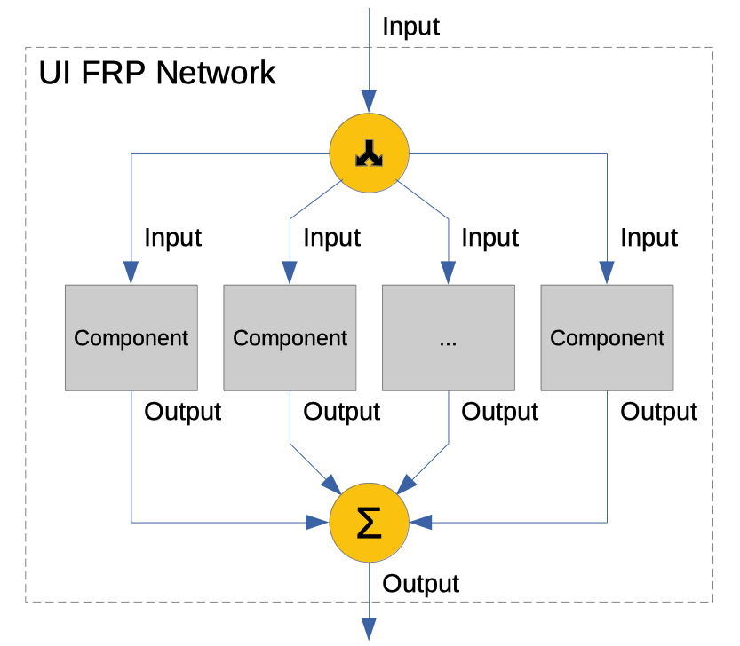
(The final output of the network should obviously be a Panel type output.)
The components used to form the UI can be atomic units or they can be compositions of other components, and how they're combined determines the layout and behavior of the UI.
A few general functions were written to combine components of different types in various ways:
fanThroughsimply replicates the input across a list of homogeneous components and combines their outputs.integrateFeedbacktakes a Control and a Panel as arguments, routes the input through them both and combines their outputs together.layeredPanelandsplitPanelboth take a number of Panel components, route the network input through them, then combine their outputs, accumulating the visual portions so they're situated on the screen correctly.splitPanelalso modifies the input stream on its way to the Panels to implement things like mouse focus and to react to window size changes.
Using just these functions a decently sophisticated UI can be assembled from components as can be seen in this code for the editing screen:
{-# ANN module "HLint: ignore Redundant bracket" #-}
editScreen
  :: (Monad m, MonadFix m)
  => Word -> Word -> PanelContext Model.Status -> EditScreen m
editScreen resizeBarSize navBarHeight context = trackPanelContext context >>>
  -- Lisp mode!
  (integrateFeedback
    (fanThrough
      [ autoscrollControl   -- for scrolling the view along with the playback cursor
      , pagingControl       -- home, end, page-up, page-down reactions
      , playbackControl     -- play/pause
      , quitControl         -- self-explanatory
      , stateControl ])     -- for reacting to save and undo/redo inputs
    (splitPanel (Fixed SizedBottom statusPanelHeight)
      (splitPanel (Expandable SizedBottom navBarHeight resizeBarSize)
        (viewPanel)         -- waveform view; uses more combining functions internally
        (viewControlPanel)) -- view controller; uses more combining functions internally
      (statusPanel)))
(Note that a Lisp-style syntax was used here since the nested syntactic structure seems to better reflect the UI layout in code than a more Haskelly syntax did -- I'd tried using variables in a where clause but it felt less clear.)
The result of the editScreen function is a processing network that can be applied to the UI's inputs to produce UI outputs, as shown in the previous section.
Interlude: netwire
Before we continue with the main exposition, some knowledge of the FRP library used in this application should be introduced.
The library I eventually settled on using is netwire 1, an arrowized functional reactive programming library. I chose it since it seemed to have most if not all of the features I'd need to create the UI. I'll try to explain everything you need to know about this library for you to follow along below, but if you'd like more information on or examples of it I found the following resources useful:
- Novice netwire user
- Getting started with netwire and SDL
- Asteroids in netwire
- Almost a netwire 5 tutorial
- Netwire 5 vs Elerea
There are a few basic concepts you'll need to know to understand the content in the following sections:
The stream-processing type of the netwire library is the Wire, representing a transform from an input stream to an output stream. This is the type that contains state in a network.
In the code snippets below we'll be using a simplified type-signature for this type, Wire m i o where:
mis a monadiis the type of value in the input streamois the type of value in the output stream.
Streams/signals can come in one of two flavors in netwire: regular value streams (which are continuous), or events (with which there can be data or no data on a stream at any point in time). The code for this UI uses both, sometimes simultaneously.
Another concept that I'll mention but that I don't think you'll need to know for this discussion is inhibition, which is when a continuous stream ceases to produce any output values.
UI Components as State-Machines
Since components are the reactive stream-processing elements of this application, this means that they're implemented using Wires.
As alluded to above, the components used to create the UI exhibit different behaviors, and for many of them their behaviors can change over time, e.g., depending on whether the user is interacting with the component or not.
In more sophisticated cases, this requires components to be able to keep track of and change state in some way, which means that our Wires need to be able to do the same.
Netwire provides a few ways to do this sort of thing, so it took me a while to determine the best approach for this application. What I ended up using was the delayed switch function:
dSwitch :: Monad m => Wire m i (o, Event (Wire m i o)) -> Wire m i o
This function takes a Wire as an argument that it uses to process an input stream, emitting the regular stream-output values issued by the wire as its own outputs. It does this up until there is an Event output from the wire, after which it switches to behave like the Wire carried as the event payload.
Using this function I was able to divide components into discrete operating states and switch between them in response to user input events, yielding different behaviors.
To facilitate this, a convenience wrapper was written around dSwitch, named mealyState 2. This function takes two functions as arguments: one to produce the stream output for the state and one to produce a new state to transition to, when appropriate. Both argument functions are run on values from the input stream to create the output dSwitch expects:
mealyState :: Monad m => (i -> o) -> (i -> Event (Wire m i o)) -> Wire m i o
mealyState outf transf = dSwitch (arr (\i -> (outf i, transf i)))
Using this wrapper function each state of a component then consists of at least three pieces: a value representing the state, an output function, and a transition function.
Here's an example state from the main waveform editing component:
normalIdle :: Monad m => EditScreenPanel m
normalIdle = mealyState normalIdleOutput normalIdleTransition

normalIdleOutput context =
  UIOutput
  { feedbackOf = ...  -- feedback for updating the Model
  , generatorOf = ... -- function for generating output for the View
  }

normalIdleTransition context =
           (combinedCtrlKeyEvent Down context              $> adjustmentIdle)
  `mergeL` (keyEvent MetaAlt Down context                  $> precisionIdle)
  `mergeL` (buttonInBoundsEvent b LeftButton Down context  $> normalPrimed)
  `mergeL` (buttonInBoundsEvent b RightButton Down context $> normalOperationPrimed)
  where
    b = boundsIn context
normalIdle (a wire) is the state itself; normalIdleOutput is the output function and normalIdleTransition is the transition function.
The output function emits the output stream values of a component and is component-dependent, so we won't discuss the particulars here, but the form of the transition function is pretty consistent in this codebase and I'd like to touch upon what it's doing.
The code of the transition function here is organized like a table, with mappings from an input event (on the left of each $>) to the state that should be gone to when that event occurs (on the right).
What's really happening here is the events emitted by the functions on the left are having their payloads overwritten with the Wires on the right by the $> Functor operator, thus becoming the Wire-carrying events needed to prompt a transition in the dSwitch function. These events are merged together by the calls to the mergeL netwire function to give the final transition event returned by the transition function, if any.
By organizing the components into states like this some pretty complex behavior can be implemented while still keeping the code decently manageable.
Data Streams
At the bottom of all of these layers are the data streams.
To review, the UI network's input stream consists of user input from the View and the state of the Model, and the output stream contains a description of what to display for the View and updates to run on the Model.
While some aspects of the transformation from the former pair into the latter is component-dependent, there are still other general aspects of it that I would like to talk about.
First, the input side.
In my initial approach to processing the user input from the View I was running filters in many of the components to ramify the input data into different streams, to keep track of things like meta-key states, mouse position, mouse-button states, etc.
This worked, but it was suboptimal: much of the same code was repeated across multiple components since the components needed to keep track of similar things, meaning there was duplicate processing taking place, and the code for it was slow because it was using the proc syntax, which I'd read currently desugars to less-than-optimal arrow code -- some experimenting with arrow-qq in a branch confirmed this.
So, some refactoring took place.
Now, a single stage of input processing is done in the trackPanelContext arrow which records all of the relevant positions, sizes, and key/button states the components need into a single object that gets fed to the UI network as an input context. This helped simplify things and improved performance for the user-interface.
The Model state is added to this context as well and is carried through the UI network pretty-much unmodified.
Now for the output side.
In the last post it was mentioned that update messages for the Model changed from being distinct message constructors to just being function calls. This was a boon when it came to combining the output streams of components together because all that had to be done to combine the Model update portion was to compose the functions together, meaning multiple updates can be generated by the UI and applied all at the same time. If no update is produced by a component, the identity function can be returned/used.
The output for the View is a tree representing the layout of the UI. (This is what gets generated after the delay by the function that's produced by the UI operation and applied to the Model's state.) The structure of this tree is determined by how the components are combined in the UI network (by the layeredPanel and splitPanel functions), and the contents of the tree (which itself is generic) are objects produced by the components that tell the View what to draw for each particular region of the screen.
Thus the output for the View is generated each frame, rather than continuously existing and being updated whenever something changes, which means it's probably not as efficient as it could be.
Analysis
This setup does a pretty good job, but certain aspects of it cause it not to be as as flexible as a regular GUI framework, and other things just strike me as code smells; I thought I'd take a moment to discuss these things here.
External Modification
Currently, modifications to the UI cannot feasibly be made by an external actor. The layout can't be changed, and component behaviors cannot be swapped-out, added, or removed. This is because the structure of the UI is determined by the structure of the FRP network.
All changes to the network are currently affected either within it or by replacing it completely. Messages to update it could be sent in as a sort of input, but that seems like an ill-advised way to make modifications, as does attempting to manipulate the structure of the network itself (which should be possible since the constructors of the Wire type appear to be public).
The layout tree produced by the network could be transformed after generation, but then it would be out of sync with the behavior of the network.
Maybe with a different FRP library it'd be possible to make changes from the outside, or perhaps using something crazy-fancy with lenses or zippers, but I don't know that there's a simple solution at the moment, which means that this method of coding a UI is pretty static.
Events
Those who've done GUI programming in other environments like web front-ends will be used to how user interactions flow through the UI in events. The reactive environment feels similar to this, but more limited since it's just inputs-to-outputs.
Often events in a GUI framework will have different phases, such as "capture" and "bubble", and will have other features like the ability to be cancelled, but to have that in a reactive environment you'd need to implement it on top of everything else. It feels like such analogs should be possible in FRP, but I've not spent the time yet to research them.
Knowledge of the Outside World
Components in this framework know where they are located on the screen absolutely, rather than being positioned relatively, and that feels like it might be giving them too much knowledge of their environment.
Contrapositively, the way things are written now the components are not aware of mouse movement outside of their bounds, which I could see being useful for them to know (e.g. when a user is interacting with a component and accidentally strays from its bounds, but didn't mean to, it might be nice for the component to keep on working).
How it is to Use
Despite having some detractive qualities, this technique feels pretty nice to program in: the compositional nature of assembling components together makes it feel like I'm using a specification language for the layout, and using state-machines for implementing the components makes coding them feel fairly clear.